The YASEP uses a 16-bits fixed-format instruction word that can be extended with a 16-bits immediate field or a 16-bits extended word. This instruction format is identical for both YASEP16 and YASEP32 : YASEP32 can use short (16-bits) instructions and YASEP16 can use long (32-bit) instructions. There is very little difference and the instruction decoder must handle both instruction lengths.
Each instruction can contain :
These fields and flags are not all used at the same time. Some combinations are impossible by construction, some others don't make sense, others can be hidden by the assembler. However, a wide variety of instructions (an opcode followed by register names, immediate data or other flags) can be written by the user. This page explains what the "instruction forms" are, how they are designed and when they are used.
An "instruction form" is named after the way it is written in assembly language. It is a sequence of letters that describe each used field :
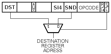
The YASEP allows only a limited number of forms. The two least significant bits of each instruction determine how to interpret the operands and other fields. The 2 bits create 4 combinations :
|
Source register Source and destination Destination register Immediate value Update (inc/dec) field Condition code |
|||||||||||||||||||||||||||||||||
| |
SND field (operand gets Negated) ↓ |
||||||||||||||||||||||||||||||||
| S | SND | OPCODE | 0 | 0 | RR: | ADD R1 R2 | |||||||||||||||||||||||||||
| 3:0 | SND | OPCODE | 1 | 0 | iR: | ADD 3 R1 | |||||||||||||||||||||||||||
| DST | IMM16 15:0 | SN | OPCODE | 0 | 1 | IRR: | ADD 1234h R1 R2 | ||||||||||||||||||||||||||
| DST | IMM20 15:0 | 19:16 | OPCODE | 0 | 1 | IR: | MOV 12345h R1 | ||||||||||||||||||||||||||
| DST | CND | code | 1 | up | 5:0 | SN | OPCODE | 1 | 1 | iRR: | ADD -25 R2 R3 ZERO R4- | ||||||||||||||||||||||
| DST | CND | code | 0 | upd | S | SN | OPCODE | 1 | 1 | RRR: | ADD D1+ R2 D3+ LSB0 R4 | ||||||||||||||||||||||
| ↑ Examples |
|||||||||||||||||||||||||||||||||
| 3 1 |
3 0 |
2 9 |
2 8 |
2 7 |
2 6 |
2 5 |
2 4 |
2 3 |
2 2 |
2 1 |
2 0 |
1 9 |
1 8 |
1 7 |
1 6 |
1 5 |
1 4 |
1 3 |
1 2 |
1 1 |
1 0 |
9 |
8 |
7 |
6 |
5 |
4 |
3 |
2 |
1 |
0 |
||
| ↑ Aux flag |
↑ Imm/Reg flag |
↑ Short/Long flag |
|||||||||||||||||||||||||||||||
The extended form contains an auxiliary flag aux to allow two sub-forms : the si4 field may be used either as a register address (RRR) or as an immediate 6 bits signed value. (iRR).
A few opcodes such as MOV have only one operand and may use the unused snd register address field to create a 20-bits signed immediate value.
Overall, instructions might use one of 6 physical forms. The assembler can make more forms available to the programmer by using certain combinations with unused fields.
Just like the Imm16 field, the Imm4 field provides a signed integer.
However, if the instruction is part of the SHL group (bit shuffling: rotations and shifts) then the field is considered as a positive integer. This preserves the compatibility between the YASEP16 and YASEP32 for the ranges from 0 to 15. For shift amounts larger than 15 with YASEP32, use the long form with Imm16 or the extended form with Imm6.
The YASEP instructions write the result of an operation (when any) to a register whose address is given by the snd or dst fields, depending on the instruction form :
This system could eventually make architectural development difficult in the far future. However, this is required to keep the instructions compact. Furthermore, in the datapath, what really counts (for performance) is the access time of the operands, not the destination address which can be computed at the same time as the ALU (a good dozen of logic levels). Since the architecture does not bypasse the pipeline (the microYASEP waits until a register is written before reading it again), we have more freedom with the fields and we can get the most out of each bit, while still keeping the instructions orthogonal. The assembler puts each field at the right position place for us.
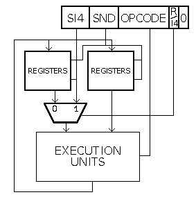
Let's start with the most simple instruction forms. The short instructions have their LSB cleared and are 16-bit long. This is enough for another flag, a 6-bit opcode and two 4-bit fields.
| 1 5 | 1 4 |
1 3 | 1 2 |
1 1 | 1 0 |
9 | 8 |
7 | 6 |
5 | 4 |
3 | 2 |
1 | 0 |
| S | SND | OPCODE | I/R | S/L | |||||||||||
| R2 | R1 | ADD | 0 | 0 | |||||||||||
| 1 5 | 1 4 |
1 3 | 1 2 |
1 1 | 1 0 |
9 | 8 |
7 | 6 |
5 | 4 |
3 | 2 |
1 | 0 |
| S | SND | OPCODE | I/R | S/L | |||||||||||
| -3 | R1 | ADD | 1 | 0 | |||||||||||
In practice, these 2 combinations can be used in 5 ways in assembly language, since any of these fields can be more or less useful depending on the kind of operation :
ADD R1 R2 ; R2 <- R1+R2This is the most common form, where si4 and snd are both register operands, and the result goes to snd.
ADD 2 R3 ; R3 <- 2+R3Another common form where si4 is used as a 4 bits signed immediate value, so snd is used as both source and operand.
A few instructions, such as OUT and PUT, use si4 as a destination address. However, since it's an immediate value, it is written before the source register.
PUT 3 R1 ; Write the content of R1 into Special Register #3
NEG R1 ; internally : R1 <- 0 - R1It's also a short way to write that both si4 and si4 fields contain the same register address. The assembler will correctly fill the operand fields if the form is correct for the opcode.
CRIT 3 ; disable the interrupts during the 3 following instructionsNot used very often but sometimes necessary. si4 is used as an immediate value and snd is ignored.
NOP ; Nop operand needed, all fields ignored.This is an extreme case where no operand is needed : si4 and snd are ignored.
The YASEP interprets the instruction as 32-bit long when the LSB is set to 1. The 16 lower bits are similar to the short forms. The second LSB selects how to interpret the following half-word :
| DST | IMM16 15:0 | SND | OPCODE | I16 | S/L | ||||||||||||||||||||||||||
| R1 | 1234h | R2 | ADD | 0 | 1 | ||||||||||||||||||||||||||
| 3 1 | 3 0 | 2 9 | 2 8 |
2 7 | 2 6 | 2 5 | 2 4 |
2 3 | 2 2 | 2 1 | 2 0 |
1 9 | 1 8 | 1 7 | 1 6 |
1 5 | 1 4 | 1 3 | 1 2 |
1 1 | 1 0 |
9 | 8 |
7 | 6 |
5 | 4 |
3 | 2 |
1 | 0 |
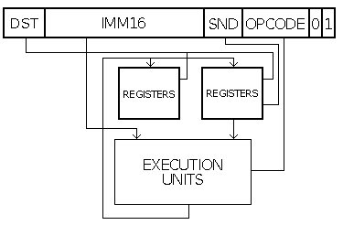
ADD 1234h R2 R1 ; R1 <- 1234h + R2This is another common form where the operands are snd (a register field) and the 16-bit immediate field. The destination register is given by dst.
GET 1234h R1 ; R1 <- SR[1234h]This form is used for the GET or MOV instructions. snd is ignored because only dst (the destination address field) makes sense for the operation. The assembler also detects when the immediate address is larger than 4 bits and issues a long or a short form.
This is also used (in conjunction with the ALIAS_IRR flag) by the ROP2 group and the ADD/SUB instructions : this is similar to FORM_iR but with a 16-bit immediate operand. dst and snd have the same value.
; Both are encoded the same way and perform the same operation :
 OR 1234h R1 R1
 OR 1234h R1
.profile YASEP32 ; the 4 MSB are ignored with YASEP16
 CALL 12345h R1
 MOV  12345h R1
MOV 12345h R1 ; R1 <= 12345h
| DST | IMM20 15:0 | 3:0 | OPCODE | I16 | S/L | ||||||||||||||||||||||||||
| R1 | 1234h | 5h | MOV | 0 | 1 | ||||||||||||||||||||||||||
| 3 1 | 3 0 | 2 9 | 2 8 |
2 7 | 2 6 | 2 5 | 2 4 |
2 3 | 2 2 | 2 1 | 2 0 |
1 9 | 1 8 | 1 7 | 1 6 |
1 5 | 1 4 | 1 3 | 1 2 |
1 1 | 1 0 |
9 | 8 |
7 | 6 |
5 | 4 |
3 | 2 |
1 | 0 |
A few instructions, such as OUT and PUT, use Imm20 as a destination address. However, since it's an immediate value, it is written before the source register.
PUT 12345h R1 ; Write the content of R1 into Special Register #12345h
The extended forms reuse the short form's structure and add 16 bits for several additional features :
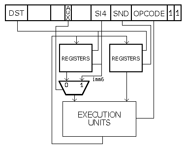
| DST | CND | code | aux | upd | S | SN | OPCODE | E/I | S/L | ||||||||||||||||||||||
| R3 | 0 | 0 | 0 | 0 | R2 | R1 | ADD | 1 | 1 | ||||||||||||||||||||||
| 3 1 | 3 0 | 2 9 | 2 8 |
2 7 | 2 6 | 2 5 | 2 4 |
2 3 | 2 2 | 2 1 | 2 0 |
1 9 | 1 8 | 1 7 | 1 6 |
1 5 | 1 4 | 1 3 | 1 2 |
1 1 | 1 0 |
9 | 8 |
7 | 6 |
5 | 4 |
3 | 2 |
1 | 0 |
ADD R1 R2 R3 ; R3 <- R1+R2si4 (R1) and snd (R2) are both register operands, and the result goes to dst (R3).
| DST | CND | code | aux | upd | Imm6 | SN | OPCODE | E/I | S/L | ||||||||||||||||||||||
| R3 | 0 | 0 | 1 | 0 | 25 | R1 | ADD | 1 | 1 | ||||||||||||||||||||||
| 3 1 | 3 0 | 2 9 | 2 8 |
2 7 | 2 6 | 2 5 | 2 4 |
2 3 | 2 2 | 2 1 | 2 0 |
1 9 | 1 8 | 1 7 | 1 6 |
1 5 | 1 4 | 1 3 | 1 2 |
1 1 | 1 0 |
9 | 8 |
7 | 6 |
5 | 4 |
3 | 2 |
1 | 0 |
ADD 25 R1 R3 ; R3 <- R1+25The 6-bits immediate field Imm6 (25) and snd (R1) are the two operands, and the result goes to dst (R3).
The extended instructions contain 7 bits that encode the condition under which the result of the current operation is written back/validated. These bits encode 3 types of predicates :
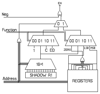
| Function | Neg=0 | Neg=1 |
| 00 | NZ (Register[cnd]!=0) | ZERO (Register[cnd]=0) |
| 01 | BIT1 (Shadow[cnd]!=0) | BIT0 (Shadow[cnd]=0) |
| 10 | LSB1 / ODD (Register[cnd] odd) | LSB0 / EVEN (Register[cnd] even) |
| 11 | MSB1 / NEGATIVE (Register[cnd] >0) | MSB0 / POSITIVE (Register[cnd] <=0) |
cnd=0 (PC)
| Fonction | Neg=0 | Neg=1 |
| 00 | Always (default) | Never (reserved) |
| 01 | BIT1 (Shadow[0]!=0) | BIT0 (Shadow[0]=0) |
| 10 | CARRY / NO_BORROW (Carry flag is set) | NO_CARRY / BORROW (Carry flag cleared) |
| 11 | EQ (Equal flag is set) | NEQ (Equal flag cleared) |
The condition codes are designed so the condition "ALWAYS" is represented with all the bits cleared (0).
All the conditions can be negated. The condition "NEVER" is created with inverting the condition "ALWAYS".
The "shadow" register is currently undefined. In the first iterations, it can be a copy of the R1 register. Later it can be configured to access I/O pins for example.
ADD R1,R2,R3 LSB0 R4 ; If R4 is even then R3 <= R1 + R2| DST | CND | code | aux | upd | S | SN | OPCODE | E/I | S/L | ||||||||||||||||||||||
| R3 | R4 | 101 | 0 | 0 | R2 | R1 | ADD | 1 | 1 | ||||||||||||||||||||||
| 3 1 | 3 0 | 2 9 | 2 8 |
2 7 | 2 6 | 2 5 | 2 4 |
2 3 | 2 2 | 2 1 | 2 0 |
1 9 | 1 8 | 1 7 | 1 6 |
1 5 | 1 4 | 1 3 | 1 2 |
1 1 | 1 0 |
9 | 8 |
7 | 6 |
5 | 4 |
3 | 2 |
1 | 0 |
The extended instruction forms contain an additional field that is dedicated to "pointer auto-update" and the format is defined since 2014-01-31. Some values might change a bit in the future (while the system is being tuned) but the bit field will not move anymore. See the justifications at Definition of the auto-update fields.
| 00 | 01 | 10 | 11 | |
| 00 | NOP | SND+,SI4+,DST+ | SI4- | SI4+ |
| 01 | SND-,SI4- | SND+,SI4+ | SND- | SND+ |
| 10 | DST-,SI4- | DST+,SI4+ | DST- | DST+ |
| 11 | DST-,SND- | DST+,SND+ | CND- | CND+ |
| 00 | NOP (do nothing) |
| 01 | SND+ (increment the source) |
| 10 | DST+ (increment the destination) |
| 11 | CND- (decrement the condition) |
The YASEP implementations that don't support this feature (for example, the microYASEP) should trigger an exception when something else than NOP is encountered.
These bits are decoded in the context of the Aux flag since it makes no sense to modify si4 when it contains immediate values. The remaining 4 or 2 bits contain the most useful combinations of parameters, which should increase code density.
Pre-incrementation and pre-decrementation are not available for architectural reasons.
Let's imagine that it was possible to pre-compute an address before the actual
operation starts, within a single instruction:
- this would increase the instruction's latency, as the memory should be fetched
and this would delay the actual execution by an unknown number of clock cycles
- the generated address could trigger a page fault or protection fault, but there
is no way to stop the instruction's execution in the middle, or even resume the pipeline
with partial data.
The post-update system follows these implicit rules:
Some combinations require special care:
ADD R1 R2 R3+ ; R3 is not incremented and contains the sum of R1 and R2
ADD R1+ R1+ R2   ; R1 is incremented only once
ADD D1+ D2+ D1+  ; A1 is incremented only once
As a consequence, only A registers can be modified by the DST field, and only implicitly by addressing its D peer.
MOV 50, R1 ; set the counter for 50 iterations
MOV 0, R2  ; clear the accumulator

  ADD R1 R2 ; add the counter's value to the accumulator
ADD -2 PC NZ R1- ; If R1 is not zero then
                 ;   - decrement R1
                 ;   - jump 2 bytes backwards and continue looping
A loop, or a code block that must be skipped, can contain up to 8 long instructions or 16 short instructions, without additional operations or registers.
The YASEP can also read and write consecutive memory words without overhead because the pointer registers A can be incremented while their associated data registers D are accessed. You can copy or modify blocks of data very easily:
MOV 50, R1       ;  set the counter for 50 iterations
MOV 2345h, A1    ; set the source pointer
MOV 6789h, A2    ; destination pointer

  MOV D1+ D2+    ; copy one word
ADD -4 PC NZ R1- ; If R1 is not zero then
                 ;   - decrement R1
                 ;   - jump 4 bytes backwards and continue looping
This feature also makes stack access easy, PUSH and POP instructions are emulated. Since there is no single hardware-defined stack, the YASEP can supports languages with multiple stacks such as FORTH.