Summary : a few cheap SMT resistors with the right value, soldered on specific bits of the data bus of a HD44780-compatible module, indicate the display's character configuration and resolution, providing enough informations for the CPU's handling routines.
The issue that I try to solve with this "proposed protocol" is simple : the HD44780-compatible LCD modules have many flavors and resolutions, but they all look the same to the software that can't guess the actual display resolution and addresses without user intervention. This can become annoying when, like me, you have a growing collection of modules from very different manufacturers and models, saved from old hardware or bought from brokers or on eBay.

The resolutions that I have now are 1x8, 1x16, 1x20, 2x16, 2x20, 4x20. From this page and this one (plus some stores), I know that there are also 1x40, 2x8, 2x24, 2x32, 2x40, 4x16 and 4x40. And there are also some variations !
It would be interesting to have a single common set of routines that handle all of these resolutions, but they must know what is hooked. Usually, one would use a set of jumpers or an EEPROM byte to specify the resolution so the software reads this value, adjusts the routines and initialises the LCD module accordingly. Unfortunately, software and hardware constraints may make this unpractical or risky (for example, the jumper is not updated with the LCD module). And all known and trivial methods require user intervention and care. It's now the 21th century, guys, so let's do something modern and smart :-)
This is not a tutorial and there are better resources everywhere. The reader must be familiar with these unintuitive and strange modules.
The system is meant to contain a microprocessor or microcontroller that is tied to a HD44780-like module with dedicated low-speed pins. Typical applications use a PIC, an AVR or a parallel port (lcdproc-style) for control. My planned applications use a FPGA, which is the same category of circuitry and technology.
The number of required pins is often reduced with the "write-only, nibble mode" where only writes are performed as two consecutive 4-bit data packets :
The microcontroller and the LCD module could be running both with 3.3V or 5V, or from different power rails. Backlight can be present or absent.
The idea is to solder a few SMT resistors as "pull-downs" on the bits 4 to 7 of the data bus. The pins where they are soldered determine the module's resolution, which can be read by the host processor. The data bus is only 4-bit wide and provides 16 combinations, which is just enough for our purpose. This bus should be readable by the host processor, but this does not require an additional pin (since data port direction is an internal signal of most microcontrollers).
This is mechanically possible because SMT resistors (in 1208, 0805 or even 0603) are smaller than the 0.1" pitch of the module's pins (on a standard display). If only one pin is to be pulled down, a standard 1/4W "through-hole" resistor could also be used.
"Conversion" of an old module requires some soldering skills that can't be realistic in high volume applications but then a custom module could be built. In the future, new modules could include the pull-down resistor(s) as an option, or with dedicated soldering pads. Note that the pull-down configuration is specific to a module, since most controller circuits (HD44780 and clones) can be used for different resolutions.
The method is electrically backwards-compatible with all known protocols and interfaces. For example, it works with mixed-voltage systems, and a modified LCD module works in both 4 and 8-bit wide protocols, with WR used or not.
The only known disadvantage is the additional static current drawn, for which three further enhancements are proposed here. They refine and complement the first idea so please read them all :-)
The resolutions 1x8, 1x16, 2x16 and 2x20 seem to be most used so they should have the least resistors.
Note: the very large resolutions (like 4x40) require two almost independent controller chips. They share the R/S, RW and data bus but they have their own E signal. This is not covered here.
Summary :
         bits 7
value   downto 4    function
  0     "0000"    Reserved (extension)
  1     "0001"    4x16
  2     "0010"    4x40
  3     "0011"    1x20
  4     "0100"    Reserved (alternate configuration for a resolution)
  5     "0101"    1x40
  6     "0110"    2x24
  7     "0111"    4x20
  8     "1000"    Reserved (alternate configuration for a resolution)
  9     "1001"    2x8
 10     "1010"    2x32
 11     "1011"    2x20
 12     "1100"    2x40
 13     "1101"    2x16
 14     "1110"    1x16
 15     "1111"    1x8 / fallback / LCD absent
(Each "0" on the data bus is implemented by a single pull-down resistor)
The system should work with 3.3V or mixed voltages. Most HD44780 are compatible with the 3.3V but the value of the pull-down resistor must be correctly chosen.
Note 1 : CMOS pins draw more current when their input is close to Vdd/2 so there is a compromise to find : either the pull-down resistor is larger and the port consumes more current, either the former is smaller and draws more current but the port is closer to the ground rail and consumes nothing. So don't be tempted to increase the resistor's value, because its effect is mitigated by the following idea.
Note 2 : I have used the "typical" value of 125μA as provided by Hitachi when the module is powered by 5V. With this voltage, the maximum pull-up current is 250μA. From 2.7 to 4.5V, the typical value is 50μA and maximum 120μA. It appears that these pull-ups are just MOS transistors used as resistors, not as constant current sources, so the current depends directly on the LCD's supply voltage. In case of doubts and if power consumption is not an issue, the additional pull-down resistor's value can be as low as 4.7KΩ for example.
The Data/Instruction signal (RS) can be used instead of the Vss pin. This signal is present on all the interfaces and does not interfere with the other signals :
When no activity occurs on the LCD bus, just let if float. This is "free" in most case, when the data direction signal for all the pins is kept inside the host chip.
 (schematics here)
Note that according to the Hitachi datasheet, the E pin has no pull-up or pull-down. It is the responsibility of the host circuit to ensure that a valid voltage is present. In the following example, a high-value pull-down is added but check your datasheet and double-check the voltage by measuring it.
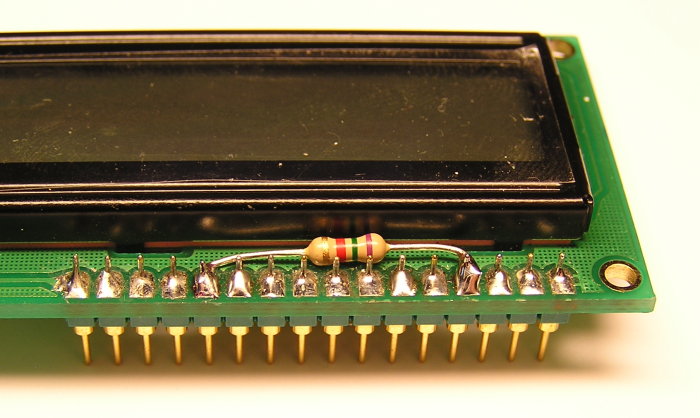
The first example takes a module bought several years ago in a store. It is a cheap but good quality clone of the original designs. I had soldered the pins back then. Adding a standard 7.5KΩ resistor was quite easy. The only potential problem is the proximity of the resistor's legs with the other pads, which could lead to shorts if very badly handled. The legs are tough, though, so no need to insulate here.
Since the display has 2 lines of 16 characters, the corresponding code is "1101". Each "0" corresponds to one resistor and each bit is numbered from right to left, from D4 to D7, so here only one resistor is required, from pin 4 (R/S) to pin 12 (D5).

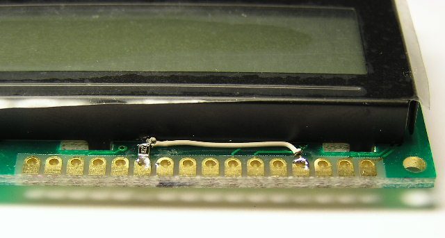
The next cobaye is an old 1x16 module with an original HD44780A QFP controller. Still in its factory bag, no connector has been soldered yet and this intervention should not keep me from doing it in the future. So I opted for a small 0805 SMT resistor, soldered on the ring of the pad, trying not to fill the plated through hole with solder.

With a resolution of 1x16, the code is "1110" so the resistor is soldered on pin 11 (D4). A fine insulated wire is then brought to pin 4 (E) and that's it. Note that the resistor is 8.2KΩ because I had nothing better.
After "enhancing" the 1x16 module, I connected it to my test devices. The module is based on a old HD44780A that is specified to work at 5V so no 3.3V test has been performed.
When R/S and RW are shorted to ground, I measure a DC current of 0.23mA in the R/S pin (this is is the sum of the pull-ups of D4 and R/S) and 0.91V on D4. When D4 is forced to 5V, I find 0.6mA on this pin, while it takes about 0.11mA to take a pulled-up pin to the ground.
This matches the previous estimations quite well and overall, with R/S and RW tied to 0V, the whole circuit draws only 0.7mA. When they are left floating (and E tied to 0V to prevent undetermined states), the consumption is down to 0.3mA, just as the datasheet states !
So if you develop a power-sensitive device, let most pins float when unused. The short pulses on the R/S pin make the pull-down-induced current negligible. A 4.7K resistor would increase the noise margin because the measured 0.91V is OK for 5V CMOS but too close to the limit of detection with 3.3V.
It seems that the module is suitable with a 3.3V host processor (in write-only mode) because the current limitation of the integrated pull-ups (added with internal diodes on the host's pins) limit the host's pin voltage. At worst, the LCD could power the host through these pull-ups, just like it is able to dimly ligh red diodes (this can be avoided by shutting down the LCD's power supply).